The Shrimp is a low-cost Arduino-compatible, microcontroller circuit that can be made for £3 - £4 (depending on how and where you source your components) and which can then be used to create digital inventions. The Shrimp has been devised by Cefn Hoile at Shrimping.it for use in 'maker' workshops in Morecambe, the shrimping capital of England.
For those of you who don't know what an Arduino is, it's a single-board microcontroller based on the Atmel ATMEGA series of chips with a software suite for programming it. Compared to other similar micro-controller boards such as the BASIC Stamp, the Arduino is much cheaper as well as having fully open hardware and open source software.

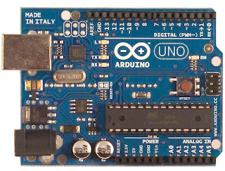
The latest Arduino board is the Uno R3 (shown above) which uses the ATMEGA328 microcontroller chip. Although it's available as prefabricated circuit board, there is even a breadboard version of the Arduino which can be self-assembled. Details are available here on the Arduino website.
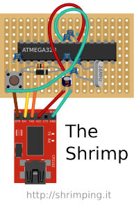
The basic components can be assembled on a breadboard or soldered onto copper stripboard in exactly the same layout to make the Shrimp. A USB to UART module (shown in red on the diagram to the left) is also needed to provide the Shrimp with a serial communications link for programming, feedback and power. Once programmed, this can be removed as long as the board is connected to a battery and feedback to the host computer is not needed.
To build a Shrimp the following parts are needed:
 |
| Click to enlarge |
- Breadboard or copper stripboard (18 strips of 11 holes minimum)
- ATMEGA328 microcontroller chip with Arduino bootloader installed
- USB to UART board, preferably with a USB extension cable
- 1 x 16mhz quartz crystal
- 1 x N4148 diode
- 1 x 10K ohm resistor
- 1 x 10uf capacitor
- 2 x 22pF capacitors
- 4 x 100nF capacitors
- 1 x tactile breadboard mounting switch
- 1 red LED
- 5 x male to female jumper wires
- Some coloured single-core (bell) wire, preferably red and green colour
Optional components:
- 3 x AA battery holder to provide power once disconnected from the computer
- 1 x 28 pin chip socket to avoid needing to solder the ATMEGA32 microcontroller chip
- 2 x right angle header pins to make connections easier using jumper cables
Assembly on breadboard using the diagram for reference:
 |
| Click to enlarge |
- Insert the ATMEGA328 chip so that it is central on the breadboard, spanning the central gap. Make sure the orientation 'dimple' mark is pointing to the left.
- Insert the five ceramic capacitors
- Insert the resistor and diode
- Insert the 10uf capacitor
- Insert the quartz crystal
- Insert the switch
- Add the three wires
- Insert the jumper wires from the USB to UART board.
When this has been done, check the circuit carefully for the components being in the correct places and push down on each wire or component leg to ensure a good connection.
When you are sure that everything is correct, insert the USB extension cable in to the USB to UART module and plug the other end into your computer. The LED on the UART board should light up as the power is applied.
You will now need to install an appropriate CP2102 USB to UART driver for your system. Windows, MacOSX and Linux drivers are all available from here. Install the drivers in the normal way for your system and if you are using Windows, check which COM port is being used e.g. COM1 to COM15 (i.e. look in Control Panel > System > Hardware devices > Ports).
The Programming Environment:
The Shrimp uses the standard open source Arduino IDE software which can be downloaded from here. Once the IDE is downloaded and installed you'll need to configure the IDE for the Shrimp, which behaves as if it is an Arduino Uno. Make sure this is selected in the Tools > Board menu as well as the correct COM port in Tools > Serial Port if you are using Windows. If you are using MacOSX, the serial port will appear as something like /dev/tty.SLAB_USBtoUART.
Hello World!
 |
| Click to enlarge |
Start by adding the red LED to the right hand (or top side) of the breadboard. The shorter leg or the leg on the flat side of the LED should go in the GND row (marked as LED on the diagram to the right) and the longer leg should go in the digital pin 13 row in the breadboard. Be careful because the pin numbers on the chip are not the same as the digital and analog input pin numbers. It's very confusing, so keep this diagram to hand always!
Now, with the Shrimp plugged in (USB to UART light on) and the Arduino IDE software running, select File > Examples > 01.Basics > Blink to load the simple Blink program as shown in the diagram below:
This will display the following code:
To upload this code to the Shrimp, click the 'Upload' button (right-pointing arrow in the top left corner of the sceeen) and then quickly press the 'Reset' button on the Shrimp breadboard. After this the red LED to blink twice and then the code will upload after first compiling. When the program or 'sketch' has been correctly uploaded, a message will be displayed in the black bottom section of the Arduino IDE window stating Binary sketch size: 1,084 bytes (of a 32,256 byte maximum).
The red LED should now start to blink under the control of the program you have just uploaded to the Shrimp. Try modifying the delay numbers to make the LED blink faster - you will need to upload it to the Shrimp again, by once more clicking the 'Upload' button followed by pressing the 'Reset' button on the breadboard. Indeed you need to do this each time you modify the program in some way.
If it doesn't work, look at the messages in the black section of the screen: if there are none apart from the 'Binary sketch size', the problem is probably with the LED itself: check that it is correctly inserted into the breadboard. If there are some other messages, the problem is either with the serial port selected (check you are using the correct port) or with the Shrimp hardware (check all the components are in the correct place on the breadboard and that all the connections are good, by pushing down on all the wires and legs).
If it does work, try replacing the USB to UART with a battery pack as shown below to untether your Shrimp from the computer, as shown in the diagram below:
Finally, here's a comparison between the breadboard and copper stripboard versions of the Shrimp:
As you can see, the layouts are identical, making it very easy to transfer the components from the breadboard to the stripboard. However, a section of each of the copper strips underneath the ATMEGA328 chip must be cut out before soldering the components in place to form a break similar to that on the breadboard. Failure to do this could damage the chip permanently. Here's a template for this:
DIAGRAM TO FOLLOW SOON


